I was trying to remotely maneuver a prototype robot I have made last week. If you happen to read it, you might know about it. I had an infrared receiver named TSOP1738 and a few different remote controls left useless from a car audio system and a TV here. I had IR LEDs as well, but to avoid unnecessary complexity I chose to use one of the remote controls over building one on my own with the LEDs. Here is a study I have made to make this thing work as I expected.
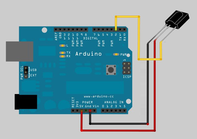
First thing to do was to check what kind of signal I was getting out of the TSOP module when I press a button on a remote control. So I wired up the module to an Arduino as shown in the above image. Pin #3 is the output of the TSOP, which is wired to the Arduino’s pin #2 and power supply is taken out of the 5V-GND header of the board. The reason why I wired up it with Arduino is that I didn’t have a separate 5V power supply here ;). Anyway I hooked up my oscilloscope’s probes to the TSOP module and pressed a button on the remote control. Bingo! I got a signal that looks like the following.
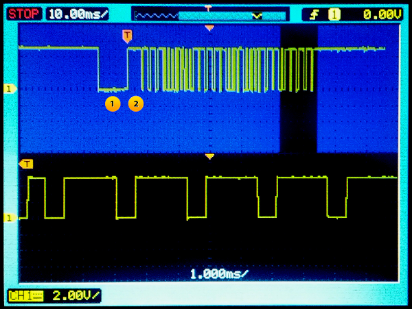
The TSOP module’s output is not bare IR pulses sent by the remote control. TSOP demodulates (removes the 38Khz carrier frequency) the signal and presents a digitally usable output. It does also block off some noise, I don’t really know much about it. Anyway, I pressed different buttons on the remote control and I got significantly similar signals all the time. These were the characteristics generally.
The start burst and the high pulse after that are marked in the image above. As I learned from this video, there are different types of encoding techniques like RC5 or the NEC protocol etc. I’m not quite sure which encoding does the remote control I have here use anyway. But I chose to code the 2000uS long pulses as logical 1’s and 600uS long ones as logical 0’s. I decoded the first button on the remote control as the following.
11100000 00011111 10100000 01011111
The second byte is the inverse of the first and the fourth byte is the inverse of the third. I think it is some mechanism to reduce errors. As I gone through encoding each keys manually, I figured out that the first 16 bits are the same for all keys. I later learned that it could be a device ID or something. Leaving that behind, the last 16 bits gave me usable data to find which button on the remote control has been pressed. See below the quite intuitive C code I used with the Arduino to decode each key’s code values.
int irPin      = 2;    //Sensor pin 1 wired to Arduino's pin 2
int start_bit  = 2200; //Start bit threshold (Microseconds)
int bin_1      = 1000; //Binary 1 threshold (Microseconds)
int bin_0      = 400;  //Binary 0 threshold (Microseconds)

void setup() {
  pinMode(irPin, INPUT);
  Serial.begin(9600);
  Serial.println("Waiting:");
}

void loop() {
  unsigned int key = getIRKey();          //Fetch the key
  if(key != 65535)  { //That is -1 aka invalid key
    Serial.println("Key:" + key);
  }
}

int getIRKey() {
  int data[32];
  int i;

  while(pulseIn(irPin, LOW) < start_bit); //Wait for a start bit

  for(i = 0 ; i < 32 ; i++)
    data[i] = pulseIn(irPin, HIGH); //Start measuring bits, I only want high pulses

  for(i = 0 ; i < 32 ; i++)  {
    if(!((data[i] > 400 && data[i] < 1000) || (data[i] > 1700 && data[i] < 3000)))  { //Filter out anything that seems  erroneous
      Serial.println("Invalid Signal");
      return -1;
    }
  }

  int key_data[16];
  for(i = 16 ; i < 32 ; i++)  //Parse them
  {
    if(data[i] > bin_1) //is it a 1?
      key_data[i-16] = 1;
    else if(data[i] > bin_0) //is it a 0?
      key_data[i-16] = 0;
    else
      return -1; //Flag the data as invalid; I don't know what it is! Return -1 on invalid data
  }

  unsigned int result = 0;
  for(i = 0 ; i < 16 ; i++)  { //Convert key_data bits to integer
    if(key_data[i] == 1)
      result |= (1<<(i));
  }
  return result; //Return key number
}
Lately I got into some inconsistency problems and noise issues. I fixed a few of them, but I still have some pain in the ass kind of problems remaining. Here’s one of them.