I have purchased an extremely cheap WiFi module based on the ESP8266 chip produced by some Chinese manufacturer. This tiny board is very popular these days in the IoT community, because of the low cost, ease of use and lower power consumption. It is available for less than $5 per unit in India through Amazon.
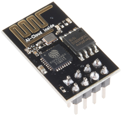
There are a number of version of boards available based on ESP8266 chip. The one I have is the ESP-01-rev02 which has 8 pins exposed from the board. The pin layout is as follows.
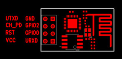
The board is relatively well soldered, and there is a printing that reads AI Cloud Inside on the board. As you might have already figured out, this is a serial device. Two of the GPIO pins are exposed along with RX, TX Vcc and GND.
The Vcc voltage requirement of the ESP-01 module is 3.3v. As I understand from other articles, the board is very sensitive to noise, and so we need to use a properly regulated 3.3v supply. For my experiment, I used an Arduino to power up the board. You may as well use an independent power supply to do the same.
If your computer already has a serial port, it should be very easy to work with the module. For safety reasons, may be use optocouplers to guard your port from external supply in case if you are doing more advanced experiments. In my case, I was using a 2013 MacBook Pro, which doesn’t have a serial port. So, I had to use a USB to TTL adapter. I purchased this for my use.
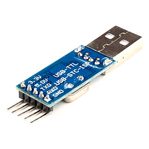
It is a PL2303 based module from Prolific Technologies. The macOs doesn’t have built in support for this chip. It needs a kernel extension driver, which you can directly download from the Prolific website. If you are running a different OS, you may find the driver at the same place as well. Here is the link to the driver download website. Once the driver is installed properly, the adapter will be listed as /dev/tty.usbserial as soon as you connect the device to your USB port.
To test the USB-TTL adapter, use a jumper to connect the RX-TX pins as shown in the following image. This configuration is usually called a RX-TX loopback.
Then connect the adapter to your USB port. For this article, I’m using CoolTerm, a very good GUI serial communication software. Alternatively, you may use screen, or minicom whichever is convenient for your usage. Open CoolTerm, click on Options, and select /dev/tty.usbserial from the device list. Switch to the Terminal tab and set the data send to line mode. Click OK to close the options window. Now click Connect, and the DTR (Data Terminal Ready) indicator on CoolTerm should be steady green. Now, type a text in the command box, and you should be able to see the response from the device in the data window above. In this case (since RX and TX are shorted), you will receive the exact same text that you have sent.
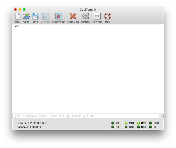
If the text you sent is not coming up in the receive window, then something is wrong with your driver or the adapter hardware itself.
The ESP module has different boot modes, ranging from normal boot to flash mode. For our normal usage, we just need to boot the module into normal mode. For that, the following configuration is needed.
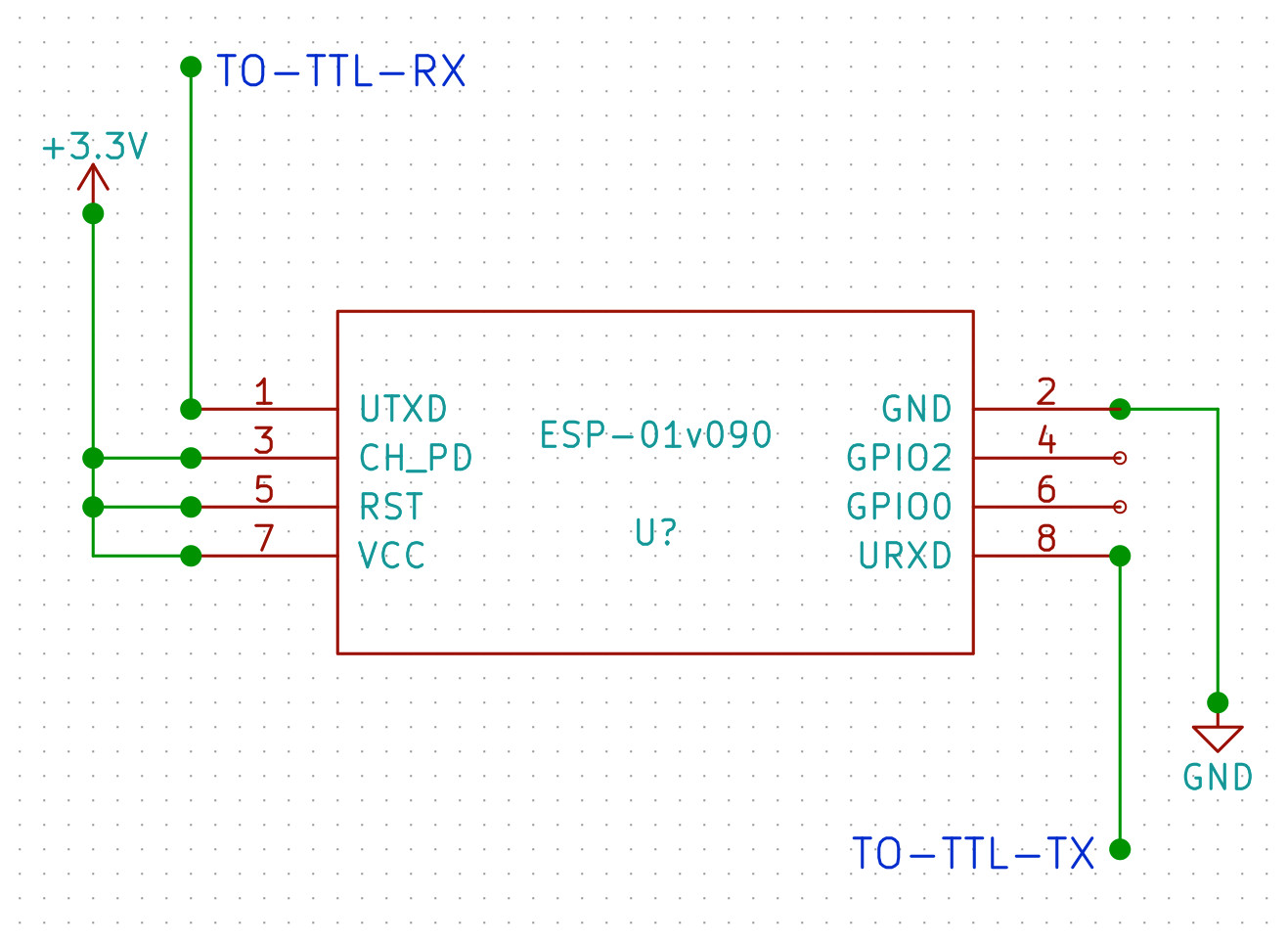
Note that the CH_PD (Chip Enable) and the RST (Reset) pins are pulled up to 3.3v (Vcc). Other configurations of these two pins are required for different boot modes supported by the module.
Note:- There are 3.3v and 5v pins available from the USB-TTL converter. But the current provided by the converter is not enough to drive the ESP module, as per some of the articles I came across. Although I haven’t tried powering the module with these pins. I will update the article if I do in future.
Now we are ready to issue AT Commands to the WiFi module. The full AT commands reference is available here. The very useful ones are listed below.
| Command | EXAMPLE | RESPONSE | NOTES |
|---|---|---|---|
| AT | AT | OK | The hello world of AT commands |
| CWMODE | AT+CWMODE=1 | OK | Set the module mode.1 —> Station Mode, 2 —> AP mode, 3 —> Hybrid Mode |
| CWLAP | AT+CWLAP | [a list] | List available access points. The response will contain SSID, MAC |
| CWJAP | AT+CWJAP=“mywifiap”,“mypassword” | OK | Join an access point |
| CIPSTART | AT+CIPSTART=“TCP”,“199.12.122.19”,80 | OK | Start a TCP connection to a web server using IP and Port |
| CIPSEND | AT+CIPSEND=20 [then data] | OK | Send 20 bytes of data. The data should follow this command |
The responses should be visible in the receive window in the CoolTerm software. If everything is working fine, the TX,RX LEDs on both the USB-TTL converter as well as the ESP-01 module should blink when you issue commands. The red LED on the ESP-01 should be steady and blue one should indicate the activity.